| Class | PMIN | PMAX | ICLASS (MIN) | ICLASS (MAX) | RCLASS |
| 0 | 0.44 W | 12.95 W | 0 mA | 4 mA | Open |
| 1 | 0.44 W | 3.84 W | 9 mA | 12 mA | 150 Ohm |
| 2 | 3.84 W | 6.49 W | 17 mA | 20 mA | 82.5 Ohm |
| 3 | 6.49 W | 12.95 W | 26 mA | 30 mA | 53.6 Ohm |
| 4 | Reserved | Reserved | 36 mA | 44 mA | 38.3 Ohm |
| Table 1. Classification Power Levels. | |||||
2012年6月30日 星期六
Hi Definition
High-definition video or HD video is any video system of higher resolution than standard-definition (SD) video, and most commonly involves display resolutions of 1,280×720 pixels (720p) or 1,920×1,080 pixels (1080i/1080p).
資料來源: http://en.wikipedia.org/wiki/High-definition_video
資料來源: http://en.wikipedia.org/wiki/High-definition_video
2012年6月29日 星期五
ONVIF
ONVIF - the market's leading standardization initiative for IP-based physical security products. Founded in 2008, the forum already has more than 330 members, representing the majority of the world's largest manufacturers of network video equipment.
The open and independent organization
ONVIF is open to all companies and interest groups who would like to participate in the work of the forum. It is a non-profit organization with the goal to create a global standard for IP-based physical security. Membership comes at three levels of engagement, and the organization has clearly defined membership rules. This ensures that:
ONVIF is open to all companies and interest groups who would like to participate in the work of the forum. It is a non-profit organization with the goal to create a global standard for IP-based physical security. Membership comes at three levels of engagement, and the organization has clearly defined membership rules. This ensures that:
- decisions within ONVIF are taken in a democratic manner
- the forum is driven by the interest of its members
- all members have equal voting rights (one company - one vote)
- there is transparency and clarity in all forum activities
The Open Network Video Interface Forum (ONVIF) is a global and open industry forum with the goal to facilitate the development and use of a global open standard for the interface of physical IP-based security products. Or in other words, to create a standard for how IP products within video surveillance and other physical security areas can communicate with each other. ONVIF is an organization started in 2008 by Axis Communications, Bosch Security Systems and Sony.
It was officially incorporated as a non-profit, 501(c)6 Delaware corporation on November 25, 2008. ONVIF membership is open to manufacturers, software developers, consultants, system integrators, end-users and other interest groups that wish to participate in the activities of ONVIF. The ONVIF specification aims to achieve interoperability between network video products regardless of manufacturer.
The cornerstones of ONVIF are:
- Standardization of communication between network video devices
- Interoperability between network video products regardless of manufacturer
- Open to all companies and organizations
An open and independent organization
ONVIF is open to all companies and interest groups who would like to participate in the work of the forum. It is a non-profit organization with the goal to create a global standard for network video products. Membership comes at three levels of engagement, and the organization has clearly defined membership rules. This ensures that:
- decisions within ONVIF are taken in a democratic manner
- the forum is driven by the interest of its members
- all members have equal voting rights (one company - one vote)
- there is transparency and clarity in all forum activities
Focus on interoperability
Product interoperability is a driving force behind ONVIF, and this means that there must be a way for manufacturers to verify their implementation and to ensure that their products are conformant with the specification. ONVIF makes this possible by providing a test specification, a test tool and a formal conformance process.
Organization and implementation
ONVIF has moved forward following the plans laid out in 2008. The first versions of the ONVIF core specification and test specification were made public in the end of 2008. Since then, several working groups within the forum have been formed to develop the specification further and to enable the members to develop and market conformant products.
ONVIF members include companies active within video surveillance, in particular network video device manufacturers (such as network cameras/IP cameras and video encoders), integrators and video management systems companies.
2012年6月20日 星期三
IP Rated Enclosures Explained
What is an IP rating?
IP (or "Ingress Protection") ratings are defined in international standard EN 60529 (British BS EN 60529:1992, European IEC 60509:1989). They are used to define levels of sealing effectiveness of electrical enclosures against intrusion from foreign bodies (tools, dirt etc) and moisture.
What do the numbers in an IP Rating mean?
The numbers that follow IP each have a specific meaning. The first indicates the degree of protection (of people) from moving parts, as well as the protection of enclosed equipment from foreign bodies. The second defines the protection level that the enclosure enjoys from various forms of moisture (drips, sprays, submersion etc). The tables below should help make sense of it:
| IP Rated Enclosures - quick find chart | |
|---|---|
A number replaced by x indicates that the enclosure is not rated for that spec. | |
| First Digit (intrusion protection) | |
| 0 | No special protection |
| 1 | Protection from a large part of the body such as a hand (but no protection from deliberate access); from solid objects greater than 50mm in diameter. |
| 2 | Protection against fingers or other object not greater than 80mm in length and 12mm in diameter. |
| 3 | Protection from entry by tools, wires etc, with a diameter of 2.5 mm or more. |
| 4 | Protection against solid bodies larger than 1mm (eg fine tools/small etc). |
| 5 | Protected against dust that may harm equipment. |
| 6 | Totally dust tight. |
| Second Digit (moisture protection) | |
| 0 | No protection. |
| 1 | Protection against condensation. |
| 2 | Protection against water droplets deflected up to 15° from vertical |
| 3 | Protected against spray up to 60° from vertical. |
| 4 | Protected against water spray from all directions. |
| 5 | Protection against low pressure water jets (all directions) |
| 6 | Protection against string water jets and waves. |
| 7 | Protected against temporary immersion. |
| 8 | Protected against prolonged effects of immersion under pressure. |
Our range
While we cover a huge range of electrical enclosures, our most common IP ratings are probably 65, 66, 67 and 68. So for quick reference, these are defined below:- IP65 Enclosure - IP rated as "dust tight" and protected against water projected from a nozzle.
- IP66 Enclosure - IP rated as "dust tight" and protected against heavy seas or powerful jets of water.
- IP 67 Enclosures - IP rated as "dust tight" and protected against immersion.
- IP 68 Enclosures - IP rated as "dust tight" and protected against complete, continuous submersion in water.
IR cut-off filter
Infrared (IR) cut-off filters are used with color CCD or CMOS imagers to produce accurate color images. An IR cut-off filter blocks the transmission of the infrared while passing the visible. This can be done with two optical techniques: absorption or reflection. Absorptive filters are made with special optical glass that absorbs near infrared radiation. Reflection type filters are short-pass interference filters that reflect infrared light with high efficiency.
資料來源: http://www.optics-online.com/irc.asp
資料來源: http://www.optics-online.com/irc.asp
2012年6月19日 星期二
網際網路控制消息協議 ICMP - Internet Control Message Protocol
即時串流協定 RTSP - Real Time Streaming Protocol
即時串流協定(Real Time Streaming Protocol,RTSP)是用來控制聲音或影像的多媒體串流協議,並允許同時多個串流需求控制,傳輸時所用的網路通訊協定並不在其定義的範圍內,伺服器端可以自行選擇使用TCP或UDP來傳送串流內容,它的語法和運作跟HTTP 1.1類似,但並不特別強調時間同步,所以比較能容忍網路延遲。而前面提到的允許同時多個串流需求控制(Multicast),除了可以降低伺服器端的網路用量,更進而支持多方視訊會議(Video Conference)。
因為與HTTP1.1的運作方式相似,所以代理伺服器〈Proxy〉的緩衝功能〈Cache〉也同樣適用於RTSP,並因RTSP具有重新導向功能,可視實際負載情況來轉換提供服務的伺服器,以避免過大的負載集中於同一伺服器而造成延遲。
The Real Time Streaming Protocol (RTSP) is a network control protocol designed for use in entertainment and communications systems to control streaming media servers. The protocol is used for establishing and controlling media sessions between end points. Clients of media servers issue VCR-like commands, such as play and pause, to facilitate real-time control of playback of media files from the server.
The transmission of streaming data itself is not a task of the RTSP protocol. Most RTSP servers use the Real-time Transport Protocol (RTP) in conjunction with Real-time Control Protocol (RTCP) for media stream delivery, however some vendors implement proprietary transport protocols. The RTSP server from RealNetworks, for example, also featuresRealNetworks' proprietary Real Data Transport (RDT).
2012年6月17日 星期日
閃爍抑制模式 Flickless
It means fix the electronic shutter speed to decrease color rolling on the camera. The 1/100 is used for PAL and the 1/120 is used for NTSC
避免因系統之頻率與燈光之頻率不同而造成螢幕閃爍之現象, 因部分國家同時使用兩種不同之頻率或有的國家雖然為NTSC系統但其電壓頻率卻為50Hz, 為避免螢幕的閃爍現象而增加此功能, 而且開啟抑制閃爍模式時能固定快門減少攝影機的色飄現象, 但入光降低使其感度也相對的降低一半
避免因系統之頻率與燈光之頻率不同而造成螢幕閃爍之現象, 因部分國家同時使用兩種不同之頻率或有的國家雖然為NTSC系統但其電壓頻率卻為50Hz, 為避免螢幕的閃爍現象而增加此功能, 而且開啟抑制閃爍模式時能固定快門減少攝影機的色飄現象, 但入光降低使其感度也相對的降低一半
2012年6月15日 星期五
CCD vs CMOS
CCD 與 CMOS,但對於大多數的同學來說,看得到的卻是一顆顆已經整合好的晶片組合!內部詳細的結構,以及到底是如何運作產生我們看到的一幅幅數位照片,且我們撇開複雜的技術文字,透過圖片比較,來看這兩種不同類型,作用卻又相同的影像感光元件。
比較 CCD 和 CMOS 的結構,放大器的位置和數量是最大的不同之處,Mr.OH! 會在下一講 CCD 感光元件工作原理(上),提及完整的感光元件作業流程。CCD 每曝光一次,自快門關閉或是內部時脈自動斷線(電子快門)後,即進行畫素轉移處理,將每一行中每一個畫素(pixel)的電荷信號依序傳入『緩衝器(電荷儲存器)』中,由底端的線路導引輸出至 CCD 旁的放大器進行放大,再串聯 ADC(類比數位資料轉換器) 輸出;相對地,CMOS 的設計中每個畫素旁就直接連著『放大器』,光電訊號可直接放大再經由 BUS 通路移動至 ADC 中轉換成數位資料。
CCD的特色在於充分保持信號在傳輸時不失真(專屬通道設計),透過每一個畫素集合至單一放大器上再做統一處理,可以保持資料的完整性;CMOS的制程較簡單,沒有專屬通道的設計,因此必須先行放大再整合各個畫素的資料。
差異分析
整體來說,CCD 與 CMOS 兩種設計的應用,反應在成像效果上,形成包括 ISO 感光度、製造成本、解析度、雜訊與耗電量等,不同類型的差異:
ISO 感光度差異:由於 CMOS 每個畫素包含了放大器與A/D轉換電路,過多的額外設備壓縮單一畫素的感光區域的表面積,因此在 相同畫素下,同樣大小之感光器尺寸,CMOS的感光度會低於CCD。
成本差異:CMOS 應用半導體工業常用的 MOS制程,可以一次整合全部周邊設施於單晶片中,節省加工晶片所需負擔的成本 和良率的損失;相對地 CCD 採用電荷傳遞的方式輸出資訊,必須另闢傳輸通道,如果通道中有一個畫素故障(Fail),就會導致一整排的 訊號壅塞,無法傳遞,因此CCD的良率比CMOS低,加上另闢傳輸通道和外加 ADC 等周邊,CCD的製造成本相對高於CMOS。
解析度差異:在第一點『感光度差異』中,由於 CMOS 每個畫素的結構比 CCD 複雜,其感光開口不及CCD大, 相對比較相同尺寸的CCD與CMOS感光器時,CCD感光器的解析度通常會優於CMOS。不過,如果跳脫尺寸限制,目前業界的CMOS 感光原件已經可達到1400萬 畫素 / 全片幅的設計,CMOS 技術在量率上的優勢可以克服大尺寸感光原件製造上的困難,特別是全片幅 24mm-by-36mm 這樣的大小。
雜訊差異:由於CMOS每個感光二極體旁都搭配一個 ADC 放大器,如果以百萬畫素計,那麼就需要百萬個以上的 ADC 放大器,雖然是統一製造下的產品,但是每個放大器或多或少都有些微的差異存在,很難達到放大同步的效果,對比單一個放大器的CCD,CMOS最終計算出的雜訊就比較多。
耗電量差異:CMOS的影像電荷驅動方式為主動式,感光二極體所產生的電荷會直接由旁邊的電晶體做放大輸出;但CCD卻為被動式, 必須外加電壓讓每個畫素中的電荷移動至傳輸通道。而這外加電壓通常需要12伏特(V)以上的水平,因此 CCD 還必須要有更精密的電源線路設計和耐壓強度,高驅動電壓使 CCD 的電量遠高於CMOS。
其他差異:IPA(Indiviual Pixel Addressing)常被使用在數位變焦放大之中,CMOS 必須仰賴 x,y 畫面定位放大處理,否則由於個別畫素放大器之誤差,容易產生畫面不平整的問題。製造機具上,CCD 必須特別訂製的機台才能製造,也因此生產高畫素的 CCD 元件產生不出日本和美國,CMOS 的生產一般記憶體/處理器機台即可擔負。
儘管 CCD 在影像品質等各方面均優於CMOS,但不可否認的CMOS具有低成本、低耗電以及高整合度的特性。 由於數位影像的需求熱烈,CMOS的低成本和穩定供貨,成為廠商的最愛,也因此其製造技術不斷地改良更新,使得 CCD 與 CMOS 兩者的差異逐漸縮小 。新一代的CCD朝向耗電量減少作為改進目標,以期進入照相手機的行動通訊市場;CMOS系列,則開始朝向大尺寸面積與高速影像處理晶片統合,藉由後續的影像處理修正雜訊以及畫質表現, 特別是 Canon 系列的 EOS D30 、EOS 300D 的成功,足見高速影像處理晶片已經可以勝任高畫素 CMOS 所產生的影像處理時間與能力的縮短;另外,大尺寸全片幅則以 Kodak DCS Pro14n、DCS Pro/n、DCS Pro/c 這一系列的數位機身為號召,CMOS未來跨足高階的影像市場產品,前景可期。
現略為鮮豔,而CANON在中低階產品色彩上並不鮮豔且有灰階現像(類似色階不完整)不但在液晶銀幕看如此,即使在MONITOR上看亦是如此
對於購買CANON-DSLR的人恐怕必須有所体認才好。(影像軟体的發達,已可運用影像軟体調到令人滿意的色調。
在長曝時感光原件產生的雜訊控制上,CANON就略為勝出,由於CMOS為較低溫的電荷原件,在10多分鐘內的長曝並不需要開啟消除
雜訊功能,這比CCD容易因長曝而溫度提高而產生紫光現像和雜訊有利多了。
資料來源:http://taiwan-photoschool.com/new_page_122.htm
遮罩 Privacy Mask
The Privacy Mask can block out sensitive areas from view, covering the areas with black boxes in both live view and recorded clips. This feature is ideal for locations with displays, keyboard sequences (e.g. passwords), and for anywhere else you don’t want sensitive information visible. You can also choose to retrieve the block-out areas during playback. The retrievable areas will be protected by password.
資料來源:http://www.tech-army.org/forum/forum_posts.asp?TID=1844
資料來源:http://www.tech-army.org/forum/forum_posts.asp?TID=1844
寬動態 Wide Dynamic Range
所謂寬動態,就是把問題集中在解決逆光環境下所產生的問題,攝影機在逆光時,因為整體入光量太大,為避免過曝,快門速度會提高,這就導致背景(高亮度區)正常了,但主體(低亮度區)卻曝光不足因此就黑掉了.如下圖

但我們主要是要看到屋內的人,窗外的景色並不重要,如何解決這問題? 就是改變測光的區域! 在D.S.P 內有個功能,就是能夠指定測光的範圍,D.S.P以這區塊來測光,因為這區塊內光線較暗,所以快門速度就降下來了,導致這區塊內曝光是正常的,但窗外就會過曝,如下圖

所謂寬動態,就是能夠兼具上面兩圖的優點,把主體跟背景都能曝光正常.
就像下面這張圖一樣.

所謂寬動態就是用一顆CCD,但是上面的每一點在單一時間內曝光兩次,一次長曝光(低快門),一次短曝光(高快門),所以每一點都有兩個資料輸出,就叫”雙輸出CCD”,正因為每點有兩個資料輸出,總資料量就比一般CCD多了一倍,因此傳輸的速度得大上一倍才能把資料送出來,所以又叫”雙速CCD(Double Speed CCD).
雙輸出CCD 送出一個長曝光及短曝光的訊號給DSP, DSP去運算再加總, 就是所謂”寬動態攝影機”.
這種方法是松下在10年前弄出來的,但弄出來後取名字就有問題了,”寬動態”(Wide Dynamic)這名詞以前已經有人用過了,再用就不稀奇了,因此就改個名稱叫”超動態”(Super-Dynamic),簡稱SD.
這種寬動態效果是做出來的,因此早期有些問題,例如無法即時處理(會有一些延遲),在明暗交接處沒法處理的很漂亮(會有毛邊),影像不自然等等….經過不斷改良,推出新DSP,就有所謂 SDII, SDIII
直到這幾年,SONY推出所謂SS-2 D.S.P 及 Double Speed CCD,才有廠家能拿來搞一搞,不過SONY還是維持它一貫傳統:D.S.P超難搞定!而且須用兩顆DSP才能實現寬動態功能,還要加個功能表(O.S.D),所以當然就賣的貴了
因此,除了松下的”超動態”,現在市面上所謂”寬動態”CCD攝影機,幾乎都是SONY SS-2 方案, 而且要兩顆DSP在上頭的.
還有,因為CCD每點”總”曝光時間是固定的,所以得配自動光圈鏡頭才行.
說到這裏,就不能不說PIXIM 方案了,它是用顆C-MOS ,DSP內包了顆ARM9處理器來處理,從資料上看來,它是透過改變C-MOS上每一點的A.G..C 來達成這個效果
所以,目前所謂寬動態機,基本上只有三種: 松下SDIII , SONY SS-2方案及PIXIM C-MOS方案.
而前面那幾張圖,只是拿來講解的示意圖,在實際使用上並不是都能達到那效果.
資料來源:http://forum.netcontrol.tw/viewtopic.php?f=17&t=211
但我們主要是要看到屋內的人,窗外的景色並不重要,如何解決這問題? 就是改變測光的區域! 在D.S.P 內有個功能,就是能夠指定測光的範圍,D.S.P以這區塊來測光,因為這區塊內光線較暗,所以快門速度就降下來了,導致這區塊內曝光是正常的,但窗外就會過曝,如下圖
所謂寬動態,就是能夠兼具上面兩圖的優點,把主體跟背景都能曝光正常.
就像下面這張圖一樣.
所謂寬動態就是用一顆CCD,但是上面的每一點在單一時間內曝光兩次,一次長曝光(低快門),一次短曝光(高快門),所以每一點都有兩個資料輸出,就叫”雙輸出CCD”,正因為每點有兩個資料輸出,總資料量就比一般CCD多了一倍,因此傳輸的速度得大上一倍才能把資料送出來,所以又叫”雙速CCD(Double Speed CCD).
雙輸出CCD 送出一個長曝光及短曝光的訊號給DSP, DSP去運算再加總, 就是所謂”寬動態攝影機”.
這種方法是松下在10年前弄出來的,但弄出來後取名字就有問題了,”寬動態”(Wide Dynamic)這名詞以前已經有人用過了,再用就不稀奇了,因此就改個名稱叫”超動態”(Super-Dynamic),簡稱SD.
這種寬動態效果是做出來的,因此早期有些問題,例如無法即時處理(會有一些延遲),在明暗交接處沒法處理的很漂亮(會有毛邊),影像不自然等等….經過不斷改良,推出新DSP,就有所謂 SDII, SDIII
直到這幾年,SONY推出所謂SS-2 D.S.P 及 Double Speed CCD,才有廠家能拿來搞一搞,不過SONY還是維持它一貫傳統:D.S.P超難搞定!而且須用兩顆DSP才能實現寬動態功能,還要加個功能表(O.S.D),所以當然就賣的貴了
因此,除了松下的”超動態”,現在市面上所謂”寬動態”CCD攝影機,幾乎都是SONY SS-2 方案, 而且要兩顆DSP在上頭的.
還有,因為CCD每點”總”曝光時間是固定的,所以得配自動光圈鏡頭才行.
說到這裏,就不能不說PIXIM 方案了,它是用顆C-MOS ,DSP內包了顆ARM9處理器來處理,從資料上看來,它是透過改變C-MOS上每一點的A.G..C 來達成這個效果
所以,目前所謂寬動態機,基本上只有三種: 松下SDIII , SONY SS-2方案及PIXIM C-MOS方案.
而前面那幾張圖,只是拿來講解的示意圖,在實際使用上並不是都能達到那效果.
資料來源:http://forum.netcontrol.tw/viewtopic.php?f=17&t=211
雜訊抑制 DNR - Dynamic Noise Reduction
3D-DNR
3DNR Technology (3D Noise Reduction) is a method of suppressing noise in an image, appearing in low light.
In video transmission systems which also include the video surveillance systems, a special place is given to noise filtering algorithms. Noise reduction is crucial for the overall functioning of the system, since the presence of noise in the video signal not only degrades the image quality, but also affects the subsequent processes of signal processing. Noise is especially harmful to the digital video that is compressed and then decompressed.
 |
Currently, methods of noise reduction can be divided into two types: 2-dimensional 2DNR, (divided then into spatial and temporal) and 3-dimensional 3DNR noise reduction.
The spatial noise reduction filter analyzes the picture only in the spatial domain, ignoring the information in the temporal direction. Temporal noise reduction filters analyze only the pixels in the temporal direction. For the temporal noise reduction, adaptive or compensatory techniques can be used. With the usage of the adaptive method the pixels that are in the same position in different frames are analyzed. Compensatory technique is based on the analysis of trajectories(彈道), based on the factual evidence received from the evaluation of movement. But 2DNR method has the disadvantage – when processing the signal, the image details become blurred. 3DNR noise reduction filter combines the advantages of temporal filters with spatial filters, but at the same time has no their disadvantages.
For 3DNR noise reduction, the method of the reduction of the additive influence of the Gaussian noise analyzing the set of consecutive video frames with the temporal filtering is used. The method determines the degree of difference between the pixels in the current frame and pixels in the previous frame. It also defines the motion vector indicative for the movement of pixels in the current frame, and a similar motion of the compensated pixel in the filtered frame. The method then estimates the distortion that affects the pixel in the current frame. As a result, the filter calculates the result at the average "weight" of pixels in the current frame in view of pixels of the second frame, taking into account the results of detection and motion estimation, motion compensation and estimation of noise.
With this method, you can get a quality video signal image under adverse lighting conditions.
雜訊比 dB
信噪比,即SNR(Signal to Noise Ratio),又称为讯噪比。狭义来讲是指放大器的输出信号的电压与同时输出的噪声电压的比,常常用分贝数表示,设备的信噪比越高表明它产生的杂音越少。一般来说,信噪比越大,说明混在信号里的噪声越小,声音回放的音质量越高,否则相反。信噪比一般不应该低于70dB,高保真音箱的信噪比应达到110dB以上。

它的單位一般使用分貝,其值為十倍對數訊號與雜訊功率比:
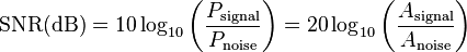
其中
 為訊號功率(Power of Signal)。
 為雜訊功率(Power of Noise)。
 為訊號振幅(Amplitude of Signal)。
 為雜訊振幅(Amplitude of Noise)。
水平解析度
用摄像机拍摄的影音信号需要在电视上播放时,需要换算成与电视画质相同的单位。而电视的画面清晰度是以水平清晰度作为单位。通俗地说,我们可以把电视上的画面以水平方向分割成很多很多“条”,分得越细,这些画面就越清楚,而水平线数的数码就越多。这个单位是“电视行(TVLine)”也称线。然而,数码摄像机以数码磁带记录的信号,在电视上播放,也换作线来计算。

    市面上一般的数码摄像机都标明了水平清晰度的大小,普遍等于或者高于500行线数。而我们看到一些佳能的数码摄像机,标着PAL制电视机625行是标称垂直分解力,其实除去逆程的50行外,实际的有效垂直分解力为575线。水平分解力最高可达575x4/3=766线。但是限制线数的主要因素之一还有带宽。经验数据表明可用80线/MHz来计算能再现的电视行(线数)。如6MHz带宽可通过水平分解力为480线的图像质量。低档家用录像机,如VHS,最多能有240线的清晰度,高档家用摄录机,如S-V而数码摄录机的记录方式是数码信号的格式,清晰度在500线以上。

    数码摄像机(DV)记录信号的彩色带宽为1.5MHz,是模拟记录方式的3倍。它采用1:5压缩比的MPEG-2(MPEG——Moving Pictures Experts Group)数字视频编码来记录现行的视频信号,水平解像力达到500线以上,与DVD 的影像质量相当,而VCD的清晰度是230线,两者相差一倍还要多。

    购买数码摄相机的时候,水平清晰度是一个很重要的参考标准。一台数码摄像机的成像质量,由它的CCD像素、CCD尺寸、感光器件个数和水平清晰度决定。如果有一天,DV带上的内容会作为电视广播媒体别播放,那么这个水平清晰度就起到了决定性的作用了。
資料來源:http://wenwen.soso.com/z/q77918419.htm?sp=1001
DPI (dot per inch)
之前所提到的電腦圖片、螢幕等等,解析度與實際顯示的尺寸間並沒有關係,因此解析度的多寡只影響到資訊量的多寡,可是對印表機與掃描器而言,掃瞄與列印的範圍是有固定大小,在一定大小範圍內若能產生更多的像素,代表畫質越細密。用來計算的單位稱作dpi,英文的意思是每英吋幾個點(像素)。
掃描器:
一般的掃描器有600 dpi及1200dpi的分別,表示對於同樣的圖片,前者最高每英吋可以得到600 pixel的資料,後者可以得到1200 pixel的資料。對一張3x5吋的照片進行掃瞄,各可得到1800x3000及3600x6000pixel的圖檔,因此一般情況下是不會用最高解析度還掃瞄東西的,可是如果要掃瞄的圖片很小,卻想得到高解析度的圖案,低解析度的掃描器就沒有辦法了。
噴墨印表機:
解析度表示該噴頭的精密程度,600dpi表示每吋可噴上600個點,因此解析度越高表示在相同範圍內可以產生更細密的墨點,列印效果越好,不過因為噴墨印表機只有四色或六色的墨水,需要好幾個墨點才能組合出特定的顏色,因此拿來印彩色圖案的話,實際可用的解析度並沒有那麼高。
dpi的意義就是提供pixel與實際尺寸的換算關係,假設我想得到一張300x500 pixel的圖片,而原本圖片的尺寸是3x5吋,那麼我掃瞄的時候只要使用100dpi就夠了。

假設我有張海報要請人印刷,印刷的解析度是200dpi,如果海報有30x50吋那麼大的話,我就需要準備6000x10000pixel的圖檔才能印出最佳的畫質,這可是非常非常巨大的圖檔,從這邊可以知道電腦印刷不是每個人的配備都玩得起的,這也是一般人用電腦自行製作型錄、畢業紀念冊、宣傳海報最常犯的錯誤,以為螢幕上800x600或是1024x768的圖送到印刷廠就可以印得漂漂亮亮,沒想到印出來都是馬賽克的方塊,主要就是解析度不夠。
資料來源:http://www.ctk.com.tw/jackweb/graphic/Knowledge/dpi.htm
資料來源:http://www.ctk.com.tw/jackweb/graphic/Knowledge/dpi.htm
2012年6月13日 星期三
What is video management software?
Video management software running on a Windows or Unix/Linux server, supplies the basis for video monitoring, analysis, and recording. A wide range of software is available, based on the users' requirements. A standard Web browser provides adequate viewing for many network video applications, utilizing the Web interface built into the network camera or video server especially if only one or a few cameras are viewed at the same time.
To view several cameras at the same time, dedicated video management software is required. A wide range of video management software is available. In its simplest form, it offers live viewing, storing and retrieving of video sequences. Advanced software contains features such as:
- Simultaneous viewing and recording of live video from multiple cameras
- Several recording modes: continuous, scheduled, on alarm and on motion detection
- Capacity to handle high frame rates and large amounts of data
- Multiple search functions for recorded events
- Remote access via a Web browser, client software and even PDA client
- Control of PTZ and dome cameras
- Alarm management functions (sound alarm, pop-up windows or e-mail)
- Full duplex, real-time audio support
- Video intelligence
2012年6月12日 星期二
RS485 serial information
RS232, RS422, RS423 and RS485 are serial communication methods for computers and devices. RS232 is without doubt the best known interface, because this serial interface is implemented on almost all computers available today. But some of the other interfaces are certainly interesting because they can be used in situations whereRS232 is not appropriate. We will concentrate on the RS485interface here.
RS232 is an interface to connect one DTE, data terminal equipment to one DCE, data communication equipment at a maximum speed of 20 kbps with a maximum cable length of 50 feet. This was sufficient in the old days where almost all computer equipment were connected using modems, but soon after people started to look for interfaces capable of one or more of the following:
Differential signals with RS485:
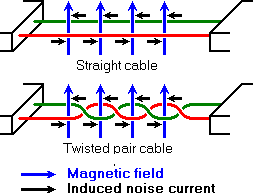
One of the main problems with RS232 is the lack of immunity for noise on the signal lines. The transmitter and receiver compare the voltages of the data- and handshake lines with one common zero line. Shifts in the ground level can have disastrous effects. Therefore the trigger level of the RS232 interface is set relatively high at ±3 Volt. Noise is easily picked up and limits both the maximum distance and communication speed. With RS485 on the contrary there is no such thing as a common zero as a signal reference. Several volts difference in the ground level of the RS485 transmitter and receiver does not cause any problems. The RS485 signals are floating and each signal is transmitted over a Sig+ line and a Sig- line. The RS485 receiver compares the voltage difference between both lines, instead of the absolute voltage level on a signal line. This works well and prevents the existence of ground loops, a common source of communication problems. The best results are achieved if the Sig+ and Sig- lines are twisted. The image below explains why.
RS232 is an interface to connect one DTE, data terminal equipment to one DCE, data communication equipment at a maximum speed of 20 kbps with a maximum cable length of 50 feet. This was sufficient in the old days where almost all computer equipment were connected using modems, but soon after people started to look for interfaces capable of one or more of the following:
- Connect DTE's directly without the need of modems
- Connect several DTE's in a network structure
- Ability to communicate over longer distances
- Ability to communicate at faster communication rates
RS485 is the most versatile communication standard in the standard series defined by the EIA, as it performs well on all four points. That is why RS485 is currently a widely used communication interface in data acquisition and control applications where multiple nodes communicate with each other.
Differential signals with RS485:
Longer distances and higher bit rates
One of the main problems with RS232 is the lack of immunity for noise on the signal lines. The transmitter and receiver compare the voltages of the data- and handshake lines with one common zero line. Shifts in the ground level can have disastrous effects. Therefore the trigger level of the RS232 interface is set relatively high at ±3 Volt. Noise is easily picked up and limits both the maximum distance and communication speed. With RS485 on the contrary there is no such thing as a common zero as a signal reference. Several volts difference in the ground level of the RS485 transmitter and receiver does not cause any problems. The RS485 signals are floating and each signal is transmitted over a Sig+ line and a Sig- line. The RS485 receiver compares the voltage difference between both lines, instead of the absolute voltage level on a signal line. This works well and prevents the existence of ground loops, a common source of communication problems. The best results are achieved if the Sig+ and Sig- lines are twisted. The image below explains why.
Noise in straight and twisted pair cables
In the picture above, noise is generated by magnetic fields from the environment. The picture shows the magnetic field lines and the noise current in the RS485 data lines that is the result of that magnetic field. In the straight cable, all noise current is flowing in the same direction, practically generating a looping current just like in an ordinary transformer. When the cable is twisted, we see that in some parts of the signal lines the direction of the noise current is the oposite from the current in other parts of the cable. Because of this, the resulting noise current is many factors lower than with an ordinary straight cable. Shielding—which is a common method to prevent noise in RS232 lines—tries to keep hostile magnetic fields away from the signal lines. Twisted pairs in RS485 communication however adds immunity which is a much better way to fight noise. The magnetic fields are allowed to pass, but do no harm. If high noise immunity is needed, often a combination of twisting and shielding is used as for example in STP, shielded twisted pair and FTP, foiled twisted pair networking cables. Differential signals and twisting allows RS485 to communicate over much longer communication distances than achievable with RS232. With RS485 communication distances of 1200 m are possible.
Differential signal lines also allow higher bit rates than possible with non-differential connections.
Therefore RS485 can overcome the practical communication speed limit of RS232. Currently RS485 drivers are produced that can achieve a bit rate of 35 mbps.
Characteristics of RS485 compared to RS232, RS422 and RS423
| RS232 | RS423 | RS422 | RS485 | |
|---|---|---|---|---|
| Differential | no | no | yes | yes |
| Max number of drivers Max number of receivers | 1 1 | 1 10 | 1 10 | 32 32 |
| Modes of operation | half duplex full duplex | half duplex | half duplex | half duplex |
| Network topology | point-to-point | multidrop | multidrop | multipoint |
| Max distance (acc. standard) | 15 m | 1200 m | 1200 m | 1200 m |
| Max speed at 12 m Max speed at 1200 m | 20 kbs (1 kbs) | 100 kbs 1 kbs | 10 Mbs 100 kbs | 35 Mbs 100 kbs |
| Max slew(扭轉) rate | 30 V/μs | adjustable | n/a | n/a |
| Receiver input resistance | 3..7 kΩ | ≧ 4 kΩ | ≧ 4 kΩ | ≧ 12 kΩ |
| Driver load impedance | 3..7 kΩ | ≧ 450 Ω | 100 Ω | 54 Ω |
| Receiver input sensitivity | ±3 V | ±200 mV | ±200 mV | ±200 mV |
| Receiver input range | ±15 V | ±12 V | ±10 V | –7..12 V |
| Max driver output voltage | ±25 V | ±6 V | ±6 V | –7..12 V |
| Min driver output voltage (with load) | ±5 V | ±3.6 V | ±2.0 V | ±1.5 V |
What does all the information in this table tell us? First of all we see that the speed of the differential interfaces RS422and RS485 is far superior to the single ended versions RS232 and RS423. We also see that there is a maximum slew rate defined for both RS232 and RS423. This has been done to avoid reflections of signals. The maximum slew rate also limits the maximum communication speed on the line. For both other interfaces—RS422 and RS485—the slew rate is indefinite. To avoid reflections on longer cables it is necessary to use appropriate termination resitors.
We also see that the maximum allowed voltage levels for all interfaces are in the same range, but that the signal level is lower for the faster interfaces. Because of this RS485 and the others can be used in situations with a severe ground level shift of several volts, where at the same time high bit rates are possible because the transition between logical 0and logical 1 is only a few hundred millivolts.
Interesting is, that RS232 is the only interface capable of full duplex communication. This is, because on the other interfaces the communication channel is shared by multiple receivers and—in the case of RS485—by multiple senders.RS232 has a separate communication line for transmitting and receiving which—with a well written protocol—allows higher effective data rates at the same bit rate than the other interfaces. The request and acknowledge data needed in most protocols does not consume bandwidth on the primary data channel of RS232.
Network topology with RS485
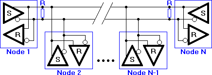
Network topology is probably the reason why RS485 is now the favorite of the four mentioned interfaces in data acquisition and control applications. RS485 is the only of the interfaces capable of internetworking multiple transmitters and receivers in the same network. When using the default RS485 receivers with an input resistance of 12 kΩ it is possible to connect 32 devices to the network. Currently available high-resistance RS485 inputs allow this number to be expanded to 256. RS485 repeaters are also available which make it possible to increase the number of nodes to several thousands, spanning multiple kilometers. And that with an interface which does not require intelligent network hardware: the implementation on the software side is not much more difficult than with RS232. It is the reason why RS485 is so popular with computers, PLCs, micro controllers and intelligent sensors in scientific and technical applications.
RS485 network topology
In the picture above, the general network topology of RS485 is shown. N nodes are connected in a multipoint RS485network. For higher speeds and longer lines, the termination resistances are necessary on both ends of the line to eliminate reflections. Use 100 Ω resistors on both ends. The RS485 network must be designed as one line with multiple drops, not as a star. Although total cable length maybe shorter in a star configuration, adequate termination is not possible anymore and signal quality may degrade significantly.
RS485 functionality
And now the most important question, how does RS485 function in practice? Default, all the senders on the RS485 bus are in tri-state with high impedance. In most higher level protocols, one of the nodes is defined as a master which sends queries or commands over the RS485 bus. All other nodes receive these data. Depending of the information in the sent data, zero or more nodes on the line respond to the master. In this situation, bandwidth can be used for almost 100%. There are other implementations of RS485 networks where every node can start a data session on its own. This is comparable with the way ethernet networks function. Because there is a chance of data collosion with this implementation, theory tells us that in this case only 37% of the bandwidth will be effectively used. With such an implementation of a RS485 network it is necessary that there is error detection implemented in the higher level protocol to detect the data corruption and resend the information at a later time.
There is no need for the senders to explicity turn the RS485 driver on or off. RS485 drivers automatically return to their high impedance tri-state within a few microseconds after the data has been sent. Therefore it is not needed to have delays between the data packets on the RS485 bus.
RS485 is used as the electrical layer for many well known interface standards, including Profibus and Modbus. ThereforeRS485 will be in use for many years in the future.
The Difference Between CIF And 4CIF Resolution
The Difference Between CIF And 4CIF Resolution
When configuring your DVR for optimal recording, there are many options you will be considering. Among them is the resolution you want to record in. While most DVR’s can record in CIF resolution (360×240) at the maximum frame rate provided by the DVR, some can also record at higher resolutions by reducing the frame rate. For example, you may be able to record on any channel at CIF resolution at 30 frames per second, but then you would probably only be able to record at 7.5 fps per second if you changed the resolution to 4CIF (704×480). (解析度增加四倍, fps少75%)You will have to decide for each camera (assuming your DVR has independent resolution settings for each channel) which resolution you want to record in. Remember, what you see is not always what you get! Most DVR’s will display live video in 4CIF or D1 (720×480) resolution, but they are often recording in a much lower resolution.
Each application has different needs. If you are using the security camera for a general overview, you may want to use CIF resolution and the maximum frame rate since detail is less important and fluid video is probably more important. On the other hand, if you are using the camera for facial recognition at the front door of your business, then you will surely want to record at 4CIF resolution, even if it means sacrificing some of the frame rate. The 4CIF image is literally 4 times larger than the CIF image and therefore can provide you with 4 times the detail. There are a couple of DVRs out there that can give you the best of both worlds, 4CIF resolution while doing 30fps recording on every channel. At this time, I only know of one unit that can offer that. It is the Ultimate Series DVR.
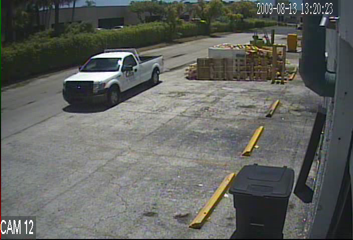
Here are 2 different images taken from an Elite Series DVR. The smaller image was from a CIF (360×240) recording and the larger image is from a 4CIF (704×480) recording. The difference between the two is the size of the image stored on the hard drive.
CIF Resolution
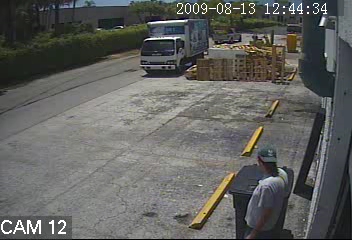
4 CIF Resolution
As you can see, the 4CIF image is much larger. It will be much easier to capture details from the 4 CIF resolution image, than from the CIF resolution image. Unless you are lucky enough to be working with a DVR that does 4CIF or D1 recording in real time (30fps) on all channels at the same time, you will need to decide for each camera, which resolution is best for that application.
資料來源:http://www.securitycameraking.com/securityinfo/2009/08/the-difference-between-cif-and-4cif-resolution/
訂閱:
文章 (Atom)